
Archive
OSPF Config (Single Area)
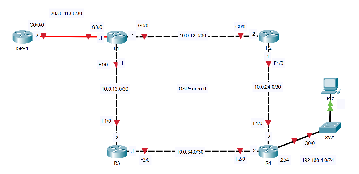
In this lab, we’ll go through the basic single-area OSPF configuration. OSPF area 0 consists of 4 routers, which we will configure so they form adjacencies with their neighbor router. You can follow along by downloading this OSPF Packet Tracer File and opening it in Cisco’s Free Packet Tracer Simulator (create a free account, enroll in one of the free courses and download the free software).
LAB STEPS:
1. Configure the appropriate hostnames and IP addresses on each device. Enable router interfaces. (You don’t have to configure ISPR1)
Router1
Router>enable
Router#conf t
Router(config)#hostname R1
R1(config)#int g0/0
R1(config-if)#ip address 10.0.12.1 255.255.255.252
R1(config-if)#no shut
R1(config-if)#int f1/0
R1(config-if)#ip address 10.0.13.1 255.255.255.252
R1(config-if)#no shut
R1(config-if)#int g3/0
R1(config-if)#ip address 203.0.113.1 255.255.255.252
R1(config-if)#no shut
Router2
Router>enable
Router#conf t
Router(config)#hostname R2
R2(config)#int g0/0
R2(config-if)#ip address 10.0.12.2 255.255.255.252
R2(config-if)#no shut
R2(config-if)#int f1/0
R2(config-if)#ip address 10.0.24.1 255.255.255.252
R2(config-if)#no shut
Router3
Router>enable
Router#conf t
Router(config)#hostname R3
R3(config-if)#int f1/0
R3(config-if)#ip address 10.0.13.2 255.255.255.252
R3(config-if)#no shut
R3(config-if)#int f2/0
R3(config-if)#ip address 10.0.34.1 255.255.255.252
R3(config-if)#no shut
Router4
Router>enable
Router#conf t
Router(config)#hostname R4
R4(config)#int f1/0
R4(config-if)#ip address 10.0.24.2 255.255.255.252
R4(config-if)#no shut
R4(config-if)#int f2/0
R4(config-if)#ip address 10.0.34.2 255.255.255.252
R4(config-if)#no shut
R4(config-if)#int g0/0
R4(config-if)#ip address 192.168.4.254 255.255.255.0
R4(config-if)#no shut
Now all 4 routers within the OSPF area have new hostnames, ip addresses, and have been enabled via the no shutdown command. You can verify that your ip address have been properly configured and enabled by using the show ip interface brief command.
2. Configure a loopback interface on each router (1.1.1.1/32 for R1, 2.2.2.2/32 for R2, etc.)
A loopback is a virtual address and is always in an up/up state.
(below I’m creating the loopback interface using a lowercase L and a zero…not a ten)
Router1
R1(config)#int l0
%LINK-5-CHANGED: Interface Loopback0, changed state to up
%LINEPROTO-5-UPDOWN: Line protocol on Interface Loopback0, changed state to up
R1(config-if)#ip address 1.1.1.1 255.255.255.255
R1(config-if)#do show ip int brief
Interface IP-Address OK? Method Status Protocol
GigabitEthernet0/0 10.0.12.1 YES manual up up
FastEthernet1/0 10.0.13.1 YES manual up up
FastEthernet2/0 unassigned YES unset administratively down down
GigabitEthernet3/0 203.0.113.1 YES manual up up
Loopback0 1.1.1.1 YES manual up up
Router2
R2(config)#int l0
%LINK-5-CHANGED: Interface Loopback0, changed state to up
%LINEPROTO-5-UPDOWN: Line protocol on Interface Loopback0, changed state to up
R2(config-if)#ip address 2.2.2.2 255.255.255.255
Router3
R3(config)#int l0
%LINK-5-CHANGED: Interface Loopback0, changed state to up
%LINEPROTO-5-UPDOWN: Line protocol on Interface Loopback0, changed state to up
R3(config-if)#ip address 3.3.3.3 255.255.255.255
Router4
R4(config)#int l0
%LINK-5-CHANGED: Interface Loopback0, changed state to up
%LINEPROTO-5-UPDOWN: Line protocol on Interface Loopback0, changed state to up
R4(config-if)#ip address 4.4.4.4 255.255.255.255
Verify loopback in two ways:
R1(config-if)#do show ip interface brief (doesn’t show mask)
R1(config-if)#do show interface l0 (does show mask)
3. Configure OSPF on each router:
– Enable OSPF on each interface (including loopback interfaces).
– (Do not enable OSPF on R1’s Internet link)
– Configure passive interfaces where appropriate (including loopback interfaces).
Router4
R4(config)#router ospf 4
R4(config-router)#network 0.0.0.0 255.255.255.255 area 0
R4(config-router)#passive-interface g0/0
R4(config-router)#passive-interface l0
The router ospf 4 command above, enters OSPF mode and assigns an OSPF Process ID of 4.
The process id is only significant to the local router. Other routers do not care about it, so they do not have to be the same on other routers.
The network 0.0.0.0 255.255.255.255 area 0 command activates OSPF on all interfaces at once. Remember: the network command uses a Wildcard Mask, so the 255.255.255.255 above is like a Subnet/Mask of 0.0.0.0
The two passive-interface cmds make interfaces g0/0 and the loopback l0 passive, (therefore not transmitting OSPF messages)
Router3
R3(config-if)#router ospf 3
R3(config-router)#network 10.0.13.2 0.0.0.0 area 0
R3(config-router)#network 10.0.34.1 0.0.0.0 area 0
R3(config-router)#net 3.3.3.3 0.0.0.0 area 0
R3(config-router)#passive-interface l0
This time, we activated OSPF on all 3 interfaces one by one. We also only needed to make the loopback interface passive because the other two interfaces need to transmit OSPF messages.
We’ll do the exact same thing on Router 2.
Router2
R2(config-if)#router ospf 2
R2(config-router)#net 10.0.0.0 0.0.255.255 area 0
R2(config-router)#net 2.2.2.2 0.0.255.255 area 0
R2(config-router)#passive-interface l0
Router1
R1(config-if)#router ospf 1
R1(config-router)#net 10.0.12.0 0.0.0.3 area 0
R1(config-router)#net 10.0.13.0 0.0.0.3 area 0
R1(config-router)#net 1.1.1.1 0.0.0.0 area 0
R1(config-router)#passive-interface l0
Above we need to “Enable OSPF on R1 (except on the Internet link)“.
Why not on the Internet Link? Because to advertise a Default Route to the other routers later, there’s no need for the other routers to know about the Point-to-Point connection between ISPR1 and R1. Example: if R2 needs to reach a server over the internet, it only needs to know to send the traffic to R1. So only activate OSPF on R1s: g0/0, f1/0 and loopback interfaces.
4. Configure R1 as an ASBR that advertises a default route into the OSPF domain.
Router1
R1(config-router)#default-information originate
R1(config-router)#exit
R1(config)#ip route 0.0.0.0 0.0.0.0 203.0.113.2
VERIFY YOUR OSPF CONFIGURATION USING THESE SHOW COMMANDS FOR OSPF:

show ip protocols
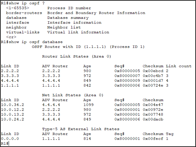
show ip ospf database
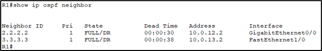
show ip ospf neighbor
5. Check the routing tables of R2, R3, and R4. What default route(s) were added?
Router2

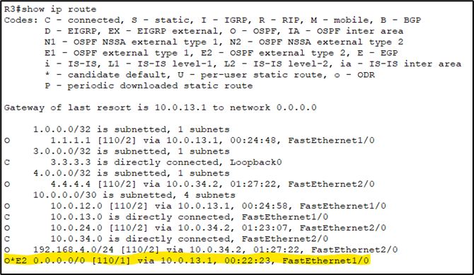
Router3
Router4
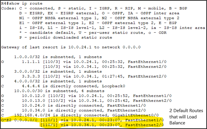
When we issue the show ip route command, we see a default route now in the routing table:
O*E2 0.0.0.0/0 [110/1] via 10.0. 13.1, FastEthernet 1/0
These default routes are being advertised by Router 1 to all other routers in the OSPF area.
Notice R4’s routing table has two default route entries and will be equally load-balanced between the two routes.
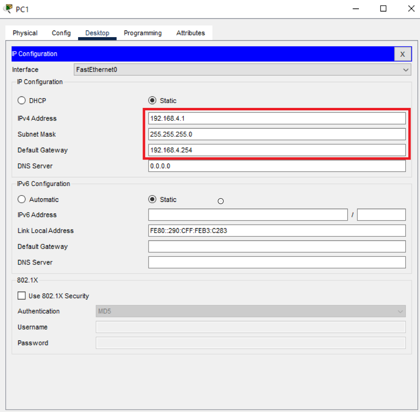
Now all devices should be able to communicate with each other. To verify this, let’s give PC1 an IP address, a default gateway and try to communicate with the external router ISPR1:


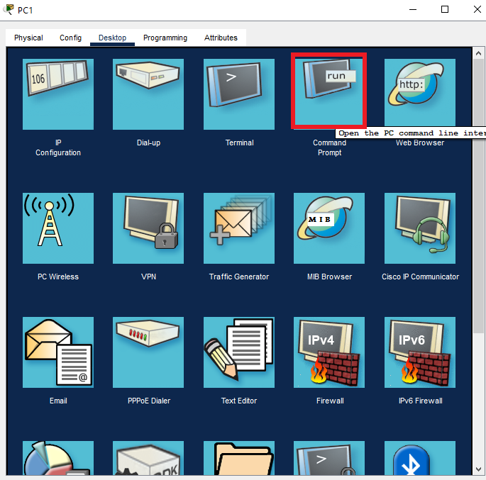

From PC1 we issued ping 203.0.113.2 in the Command Prompt and successfully communicated with ISPR1.
The first ping timed out because the ARP process needed to be initiated.
