
Archive
GRE Tunnel Configuration
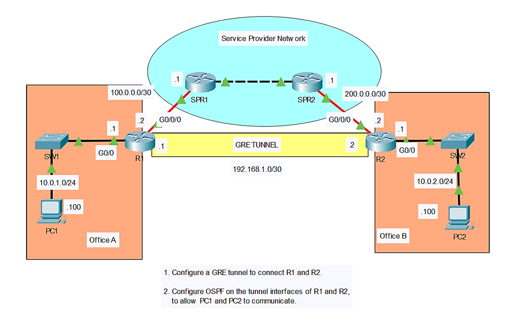
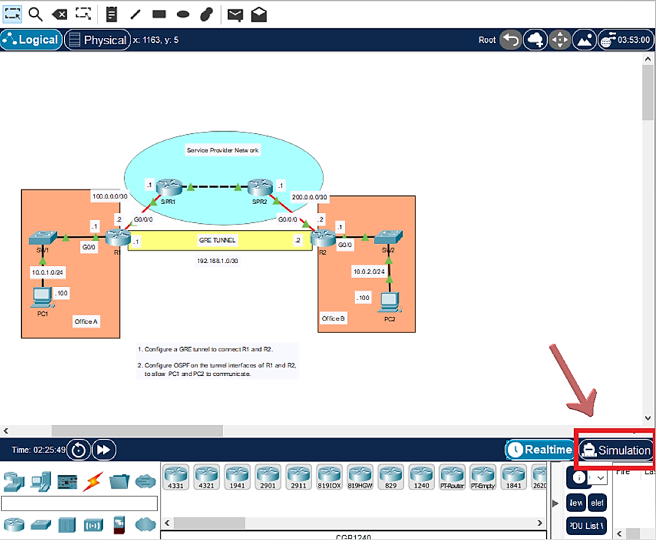
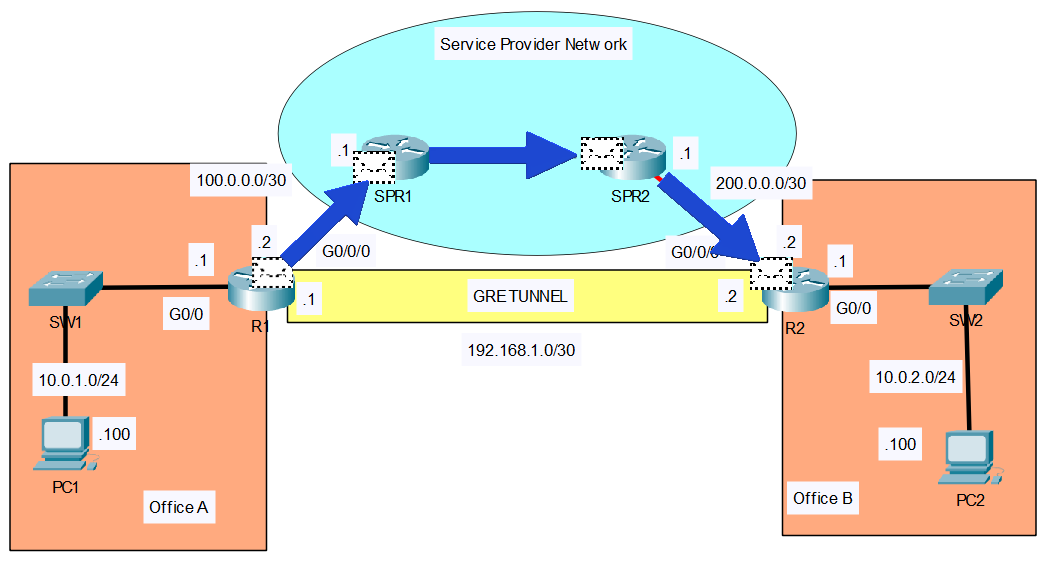
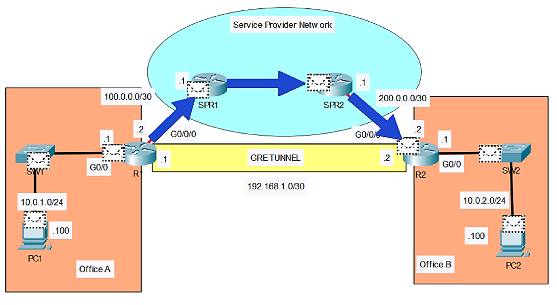
In this lab, I’ll show you how to configure a GRE tunnel between two routers. Then we will configure OSPF on the tunnel interfaces of R1 and R2, to allow PC1 in Office A to communicate with PC2 in Office B. You can follow along by downloading this GRE Tunnels Packet Tracer File and opening it in Cisco’s Free Packet Tracer Simulator (create a free account, enroll in one of the free courses and download the free software).
R1
To configure a GRE tunnel, we have to make a tunnel interface. This is not a physical interface of course, but a virtual interface, like a loopback interface:
R1(config)#interface tunnel 0
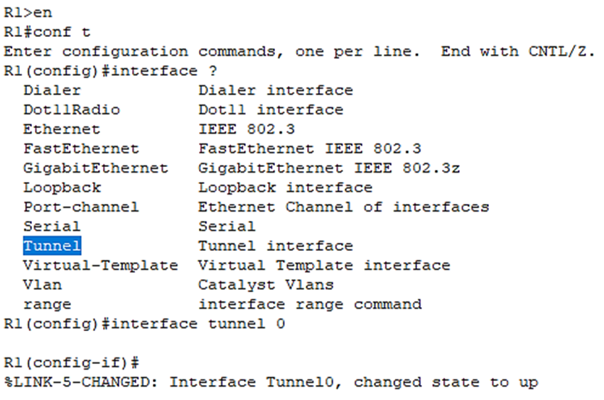
Okay, we’ve have created the tunnel interface.
Now we have to specify 3 more items to complete the GRE configuration:
- Tunnel Source
- Tunnel Destination
- IP address of the virtual tunnel itself
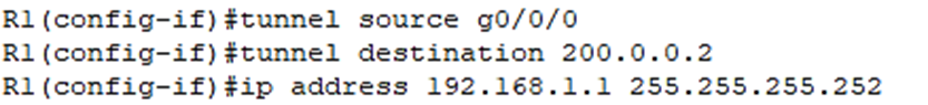
Tunnel Source: specify which physical interface on R1 will be used for the tunnel. We should use the interface connected to the service provider, which is g0/0/0 :
R1(config-if)#tunnel source g0/0/0
Tunnel Destination: specify the IP address of the other end of the tunnel, so R2. So, enter R2’s WAN interface’s IP, 200.0.0.2 :
R1(config-if)#tunnel destination 200.0.0.2
Virtual tunnel interface itself needs an IP address:
R1(config-if)#ip address 192.168.1.1 255.255.255.252
Okay, that’s all the configuration needed on R1. Below is what we just configured above on R1:
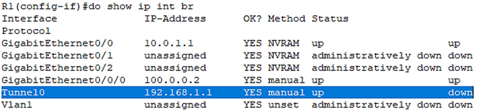
Let’s verify the virtual tunnel interface has been created:
Let’s move on to R2 and configure the other side of the tunnel.
R2
Create the virtual tunnel Interface:
R2(config)#int tunnel 0
Tunnel source (just like on R1, it will be g0/0/0):
R2(config-if)#tunnel source g0/0/0
Tunnel destination (this time it will be the IP address of R1’s WAN interface, 100.0.0.2):
R2(config-if)#tunnel destination 100.0.0.2
Finally, the IP address on the tunnel:
R2(config-if)#ip address 192.168.1.2 255.255.255.252
Let’s verify the virtual tunnel interface has been created:
R2(config-if)#do show ip int br
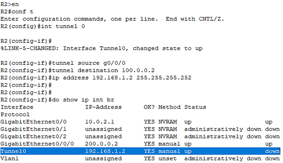
Above, we see the tunnel interface is also showing an up/down status even though we’ve configured both sides. Why is that? Let me show you by issuing:
R2(config-if)#do show ip route
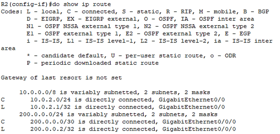
As you can see, So R2 doesn’t have a connected route for its tunnel interface of course, because the interface is still down.
It has connected routes for its physical interfaces, but we’re missing a critical route.
R2 doesn’t know how to reach the IP address we specified as the tunnel destination, 100.0.0.2.
If R2 doesn’t know how to get to 100.0.0.2, it can’t build a GRE tunnel to 100.0.0.2.
Let’s fix that:
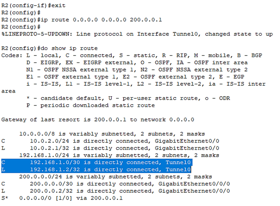
R2(config-if)#exit
Then I’ll just configure a default route:
R2(config)#ip route, 0.0.0.0 0.0.0.0 200.0.0.1
After we enter a default route which goes to 100.0.0.2, the tunnel interface comes up.
Let’s verify with:
R2(config)#do show ip route
Now we have the connected route for the tunnel in the route table:
Let’s try to ping the R1 side:
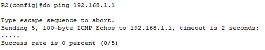
The reason for that is that we also have to configure a route on R1 to 200.0.0.2
R1
Let’s check the routing table on R1:
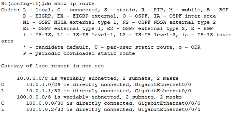
Let’s give it a default route as well:
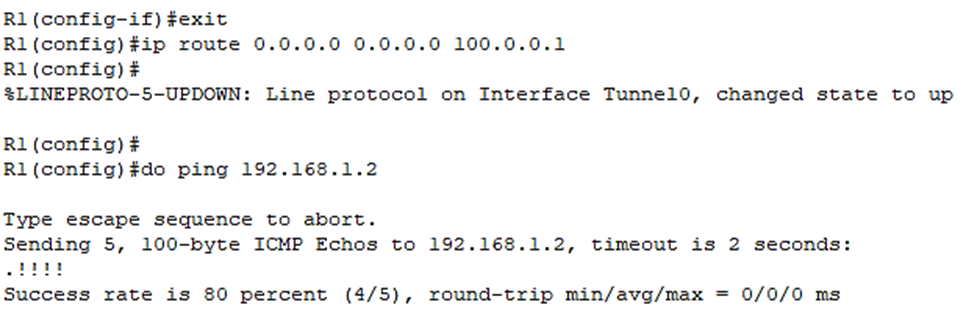
So, although R1 and R2 aren’t directly connected, they will behave as if they are directly connected through the GRE tunnel.
Let’s first look at a ping from R1 to R2 over the GRE tunnel in Simulation mode:
From R1 in Simulation issue the following ping:
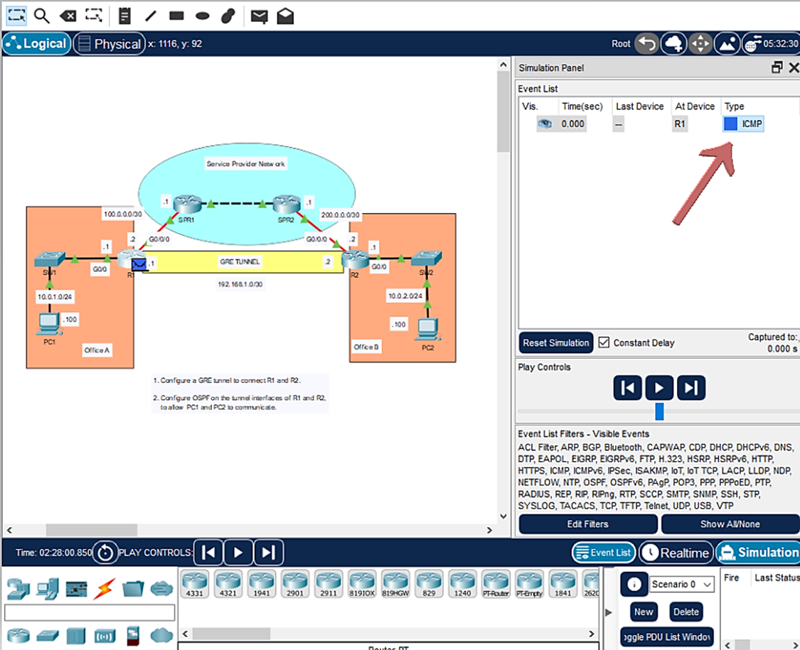
R1(config)#do ping 192.168.1.2
Then click on ICMP under Type in the right Simulation Panel to view the packet:
Then a popup window will appear labeled PDU Information at Device: R1. Select Outbound PDU Details tab:
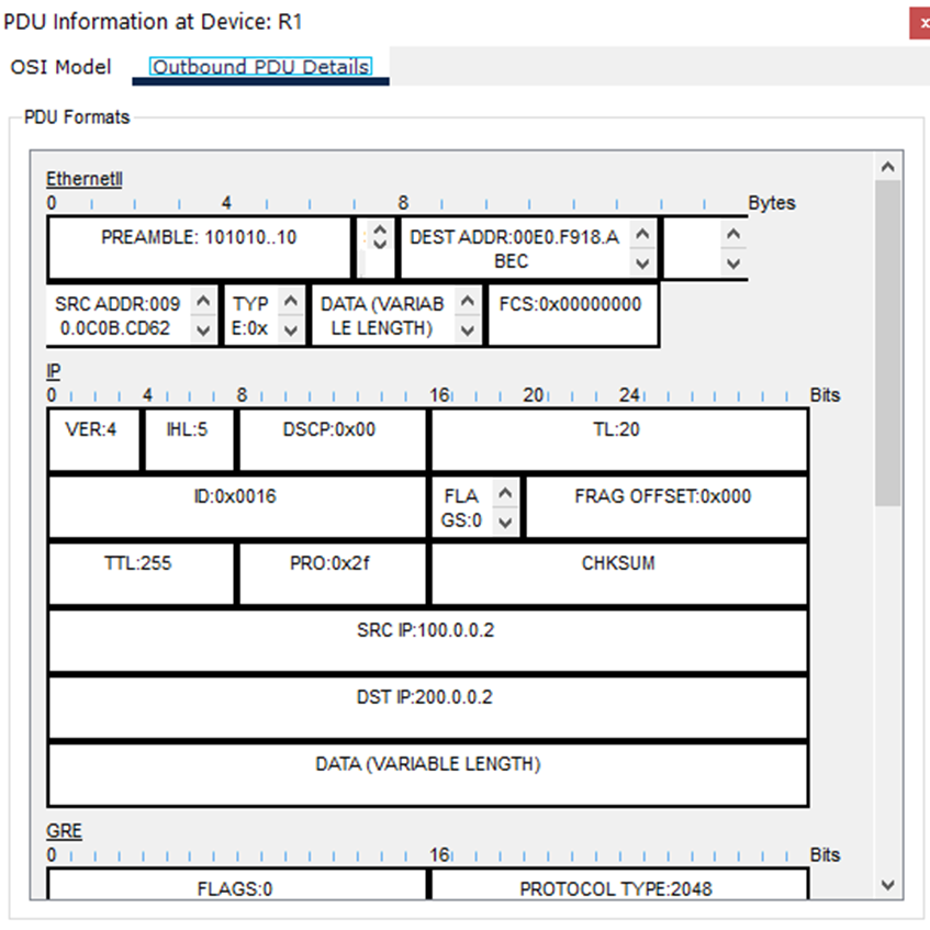
Scroll to bottom where we will see the ICMP message (the PING):
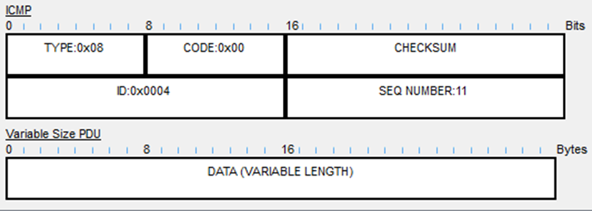
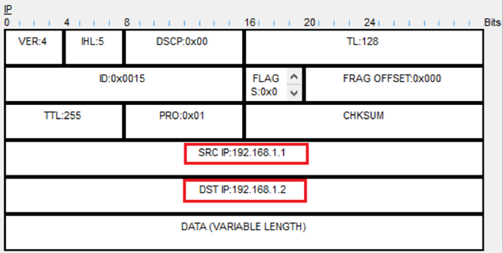
Then above that we see that the ICMP is encapsulated with an IP Header, which shows the source 192.168.1.1 and destination 192.168.1.2.
These are the addresses of the tunnel interfaces:
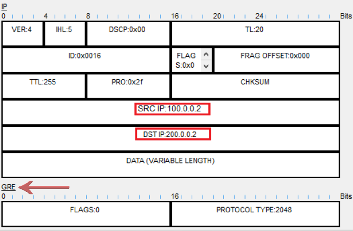
But still even on top of that, there is a GRE header, and on top of that, there is another IP header. In this outer IP header, the source IP is 100.0.0.2 (R1’s g0/0/0 interface), and the destination IP is 200.0.0.2 (R2’s g0/0/0 interface):
NOTE
The ping from R1 to R2 moves through the Service Provider Network as it would if the GRE tunnel was not configured. But as we have seen above, the communication is encapsulated several times over to create the GRE tunnel:
First, PING goes to the SPR1 router. Second, the PING goes to the SPR2 router. Thirdly, the PING finally goes to R2.
Then the PING will take the same path back a ping echo reply.
The second part of this lab is to “Configure OSPF on the tunnel interfaces of R1 and R2, to allow PC1 and PC2 to communicate.
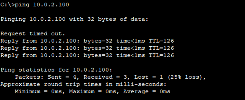
First let’s send a ping from PC1 to PC2 to show that they cannot communicate yet:
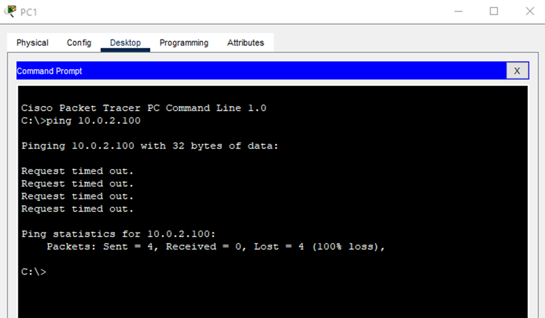
As you can see the ping’s timed out and didn’t work. But when R1 and R2 become OSPF neighbors, they will learn each other’s routes, and PC1 and PC2 will be able to communicate over the GRE tunnel.
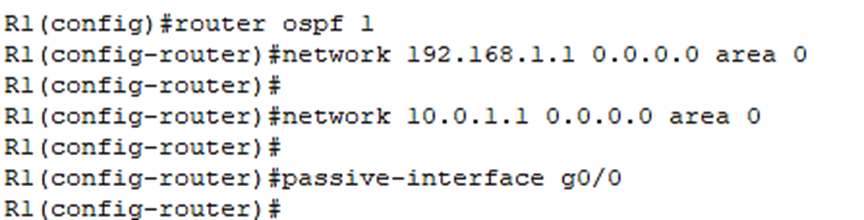
Let’s do that by enabling OSPF on R1 first by entering OSPF mode:
R1(config)#router ospf 1
The following network command enables OSPF on the Tunnel0 interface:
R1(config-router)#network 192.168.1.1 0.0.0.0 area 0
The following network command enables OSPF on the g0/0/0 interface.
R1(config-router)#network 10.0.1.1 0.0.0.0 area 0
And we’ll make g0/0 a passive interface since there are no neighbors connected to it:
R1(config-router)#passive-interface g0/0
Below are the OSPF commands we just configured:
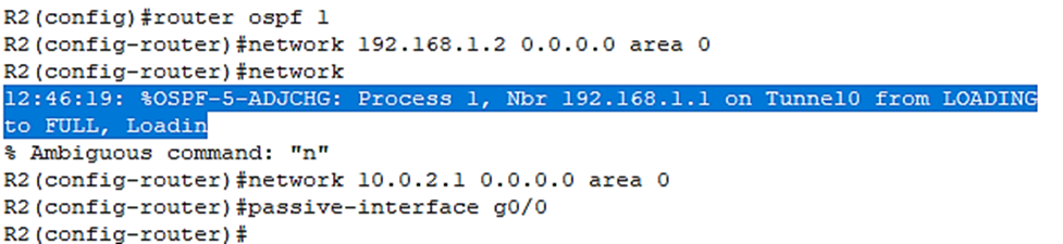
Now let’s do the same to R2:
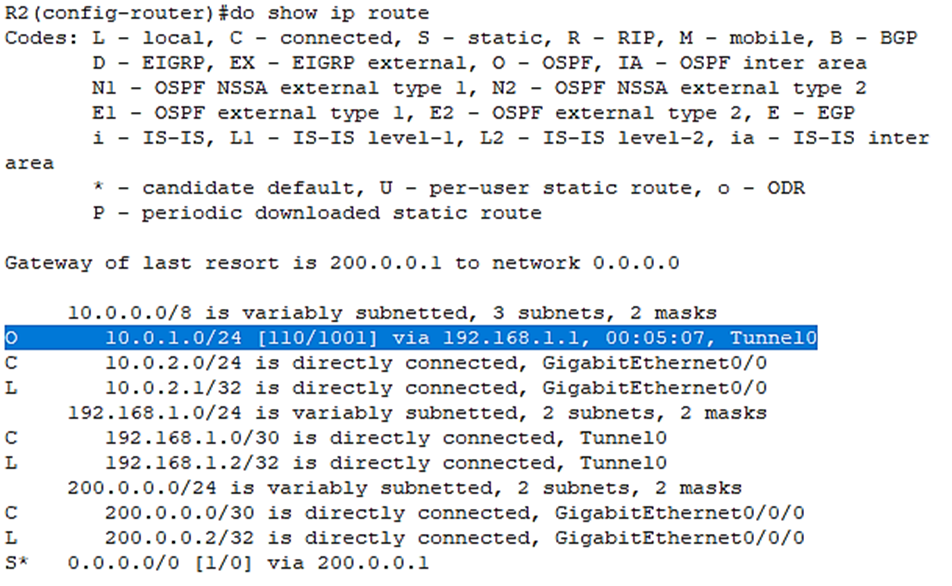
Let’s check the routes on R2 with the do show ip route command:
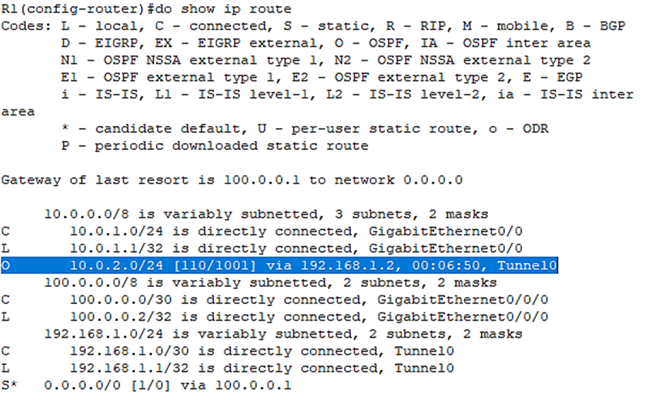
Let’s check the routes on R1 as well:
Now let’s try that same ping again from PC1 to PC2:
In this lab I’ve shown how to create a GRE tunnel between two routers and activate OSPF on the tunnel.